
I need to drill the holes which connect wires from the LED cathodes to the fretwire. I have to drill a hole through the fret slot and then mill some small channels in order to connect the wire to my other channels I already milled. I also decided to deepen some of the original milled channels so that the resistors and solder joints fit inside flush (below the surface).

Here is the wire I will be using. I think it's 22 gauge solid core wire.
Next to it is the smallest drill bit I could find.


Back side, you can see the small holes I just drilled.

I milled little slots with the router bit on the left.
I also decided to deepen the larger channels in certain spots with the router bit on the right. I tested the resistors and found them to be too fat to fit flush inside the previous channels.


I should have finished all the milling before I cut off the sides and bottom of the fretboard.
Since the fretboard now has tapered edges, I used double-sided tape
to stick the fretboard onto this block of wood.

Now to remove the fretboard from the carrier block.
This double-sided tape is a demon to get off once it sticks.
(Thus the putty knife.)

You can see the tape residue. I just used my thumbs to rub and "roll" the sticky residue off.
It's cleaner than trying to dissolve the tape residue with alcohol.
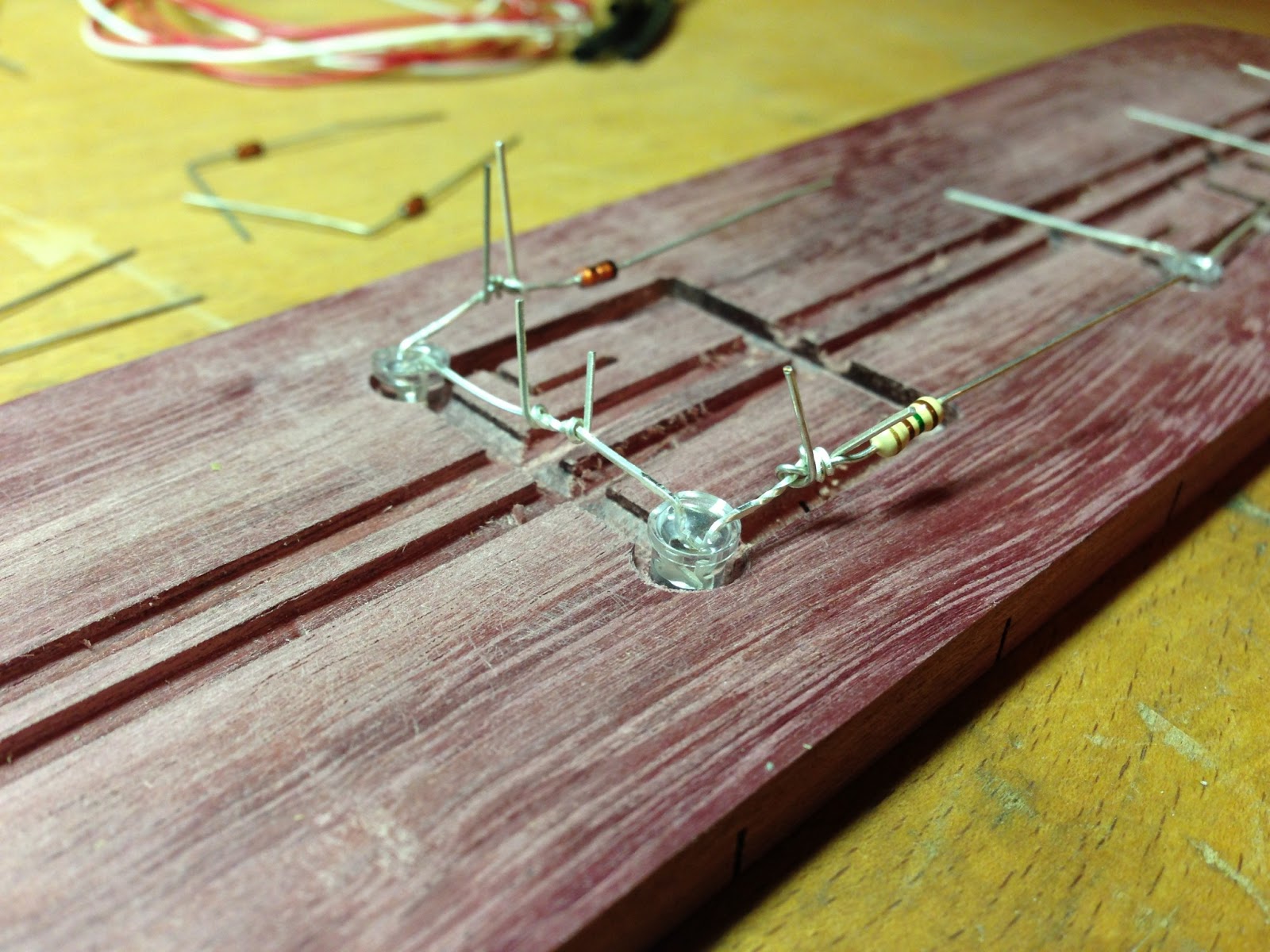
Alright, so a few days later I got around to putting the components in and soldering some of the connections. I got some 26 gauge stranded wire to use as my positive and ground lines up the middle of the fretboard. I like stranded wire because it is more flexible and durable than solid-core wire. I chose 26 gauge because it can easily handle the 200 mA this guitar neck might require, but it's also a very thin diameter.

3.0 V white LEDs, 150 and 330-ohm resistors (1/4 Watt), small signal diodes (2N914),
26 gauge stranded wire, and some heat shrink just in case I need some.

Close up of the small channels, and the sections I deepened.

First bend all the components at a 90 degree angle.

Twist the wires together.
Be gentle, if you bend an LED lead too many times it can break on you.


Here's my soldering iron. It's a Weller, and they typically cost about $40.
I like the variable temperature feature. It goes up to 40-Watts of power.
These are much nicer than the Walmart 10-Watt iron I used to have.
I really love the brass sponge tip cleaner. I will never use a wet sponge again.
Before^

After^

Before^

After^


It's a good idea to check all the LEDs at this point to make sure they still work.
OOPS! I soldered the diodes onto the LEDs before I attached the 22 gauge solid core wire that goes out the little hole!!! Not a huge problem though. I just used my de-soldering pump to remove most of the solder, and then twisted the copper wire around and then re-soldered the joints.

Here you can see I attached the small copper wire to go through the hole.

It took a little work to get it flush with the surface.
You don't want anything poking up above the surface.

Finally, I used a little bit of Krazy glue to help secure the LEDs inside once I inserted them and pushed hard with a screwdriver. The only thing I have left to do is solder the red and white wires for +9 V and ground.

A few days later, I soldered the red and white wires.

Hopefully this will give you a clear picture of how to do this yourself.


LEDs all on (underneath the bright lamp).

LEDs all on (bright lamp is off).

The last thing I have to do before I can glue the neck together is to use hot glue to secure down the components and wires so everything STAYS in place when I try to clamp it all together.
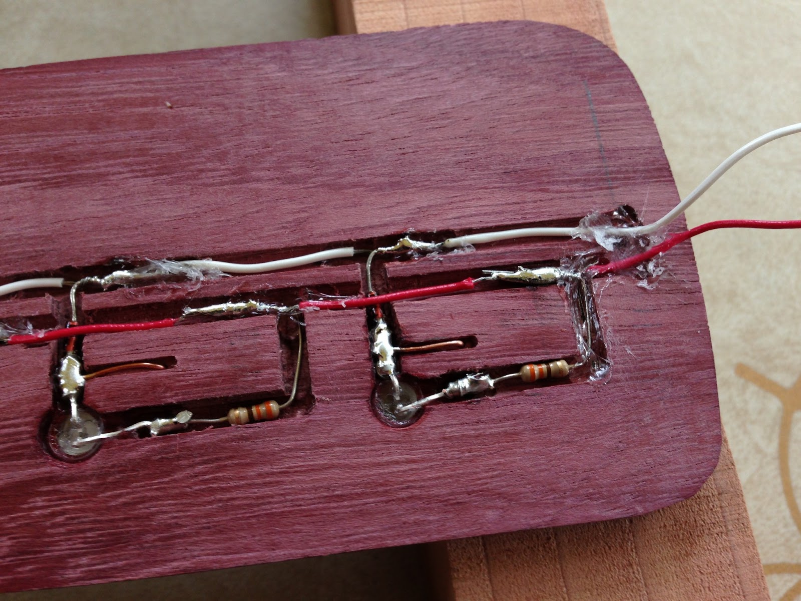
Notice the hot glue to reinforce where the red and white wires will go out through the neck.

Another test run... gotta make sure they're still working before I glue it all up!!!
Hi Nathan!
ReplyDeleteThis is fantastic. I don't know if you are still checking this, but I would really love to try it sometime. I'm pretty good with the woodworking, but I've never wired LED's before. I see how you've wired the positive and negative wires along with the resistors, but I'm unclear on how the copper connected to the frets completes the circuit to turn each led on. Do you connect the negative wire to the bridge or something? How does that work? Again, I hope you are still checking this. I think it's really creative.
David
Can you show how is the ciracuit diagram on On/off/On switch?
ReplyDeleteLove it. Have spent my career using LED's. Helpful hint. Try to run the LED's low so they will last longer. 20-30 milliamps or less for your level of brightness. Buy a high lumen LED and run it low. To hard to replace later. Buy quality. Not Radio Shack. Some come with Military Specs.
ReplyDelete